Contents
Synergy's Control Setup (Conset) functionality is designed to allow the configuration of inputs to and outputs from CR3 (CR2 NW) Control Receivers.
Outputs from CR3 (CR2 NW) Control Receivers can be used to trigger the operation of 3rd party control devices (e.g. motorised heating system valves), either directly or via MS1000 Control Units.
•Conset is a part of Synergy Version 1.7.0 or later and is only used for configuring the Control Settings for CR3 (CR2 NW) Control Receivers.
•Once configured, a CR3 (CR2 NW) is autonomous, requiring no external software or network connection to operate, though a network connection will be initially required to allow Conset to connect to the CR3 (CR2 NW) controller and configure it.
| Note: | Conset in Synergy cannot be used to configure legacy CR2 controllers, these must be upgraded to CR3 controller to enable control from Synergy; please contact your local distributor or IMC Sales for details. |
A typical application for which Conset could be used to configure Control Receiver inputs and outputs is the control of Relative Humidity (RH) for conservation purposes. For example: Two heating schemes, both employing temperature modulated control, could be defined for the building concerned: The Conservation Heating Scheme would attempt to maintain the ambient RH of the building the optimum value for the preservation of the building's fabric and contents. This value, however, may not be optimal for the comfort of any occupants of the building and so might only be used outside the opening hours and outside the open season dates unless a manual override has been set. Additionally, two temperature overrides could be used: •The maximum temperature is the highest the ambient temperature is allowed to reach. Even if the RH is above the %RH Setpoint, the temperature of the heating will not be increased. This is to ensure the room is not over-heated, leading to damage to building fabric/contents. •The minimum temperature is the lowest the ambient temperature is allowed to reach. Even if heating the zone will cause the RH to drop below the desired RH setpoint, the temperature of the heating will be increased. This is to ensure frost-protection, leading to damage to building fabric/contents. The Comfort Heating Scheme attempts to maintain the ambient temperature of the zone at the desired Steward Temperature i.e. comfortable for staff and visitors. This heating scheme would be employed during the opening hours and during the open season dates unless a manual override has been set. |
•Accessing Conset Functionality
Accessing Conset Functionality
Conset functionality is accessed from within Synergy as follows:
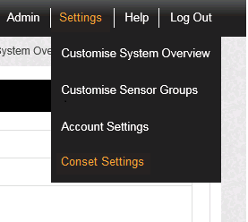
1.Click on the Settings menu bar option to display the drop down menu and select Conset Settings. See Figure 627 below:
Figure 627
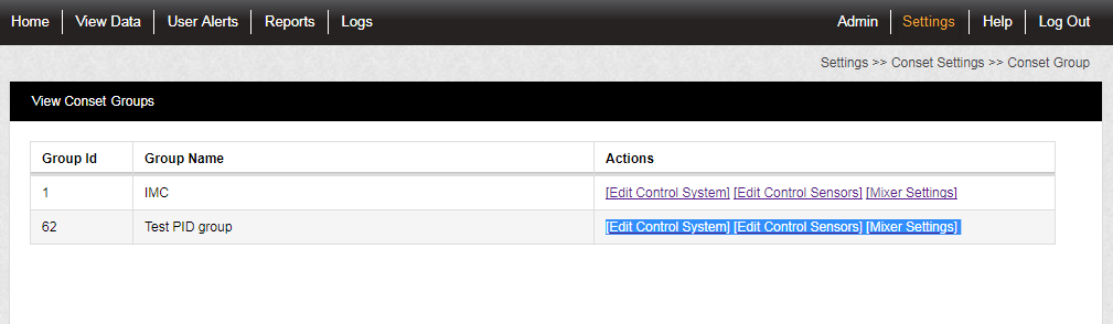
2.The View Conset Groups window is displayed, showing only CR3 (CR2 NW) Control Device Groups available for configuration by the Conset application via the [Edit Control System], [Edit Control Sensors] and [Mixer Settings] functions.
See Figure 628 below:
Figure 628
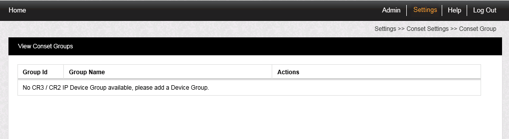
•If no CR3 (CR2 NW) Control Device Groups are available, the following window is displayed and you will need to add/define the required CR3 (CR2 NW) Control Device Groups. See Figure 629 below:
Figure 629
There are three types of setting available to a Conservation Heating Scheme in Synergy to enable it to maintain the ambient Relative Humidity (RH) of an area at the desired %RH Setpoint (+/- the RH Hysterisis Setting) through the use of temperature modulated control:
Covers the settings that will be the same for all Sensors (for example, house Opening Time and Closing Time).
Covers the settings of each individual Sensor and includes parameters such as the %RH Setpoint.
In wet heating systems where there is a primary boiler loop feeding into secondary heating circuits, the Synergy system's outputs can contribute to maintaining the ambient RH by adjusting the position of the heating installation's mixer valve according to a Proportional-Integral (PI) algorithm using the K and I values set for the control channel via Conset.
Adding or Editing Control System Settings for a Device/Control Group
1.Either:
Cick on [Edit Control System] adjacent to the required group's entry in the View Conset Groups window.
Or:
Select Edit/View Control System from the left had menu, visible if you have previously edited a Conset setting.
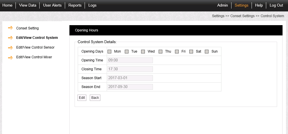
•The Opening Hours Edit/View Control System window is displayed. See Figure 630 below:
Figure 630
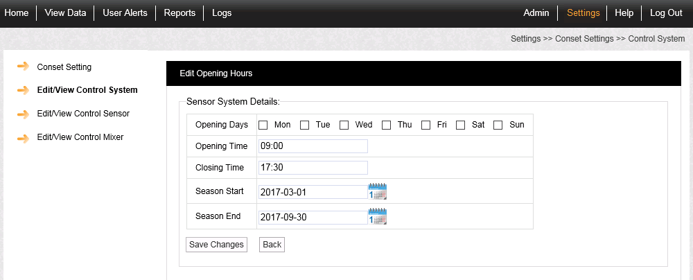
2.Click on Edit.
•The Edit Opening Hours Edit/View Control System window is displayed with the Sensor Systems Details fields activated, allowing values to be entered. See Figure 631 below:
Figure 631
•To return to the View Conset Groups window, click on Conset Setting in the left hand menu.
2.The Sensor System Details displayed define the time periods when the building is open and the Synergy system should employ Comfort Heating, using the Steward Temperature setting, instead of Conservation Heating. The time periods are defined as follows:
•Opening Days
This parameter sets the days during the Open Season when the area represented by the Control Device Group is open.
Tick the boxes adjacent to the days when the area is open.
These parameters define the hours during which the Comfort Heating will run on the selected days in the season.
Enter the Opening and Closing times in the format HH:MM (24 hour clock).
These parameters define the dates when the the Open Season starts and ends.
Either:
Enter the Season Start and Season Ends dates in the format DD/MM/YYYY
Or:
Select the required dates from the calendar displayed by clicking on the Calendar icon(s) ![]() to the right of the date entry boxes.
to the right of the date entry boxes.
•During the period specified between the Season Starts and Season Ends settings, the software will check the Opening Days and Opening/Closing Time settings and use Comfort Heating on days when the building is open.
3.When all the required values have been entered, click on Save Changes.
•You are returned to the View Conset Groups window.
Adding or Editing Control Sensor Settings for a Device/Control Group
Either:
Click on [Edit Control Sensor] adjacent to the required group's entry in the View Conset Groups window.
Or:
Select Edit/View Control Sensor from the left hand menu the left hand menu, visible if you have previously edited a Conset setting.
•The Control Sensor window is displayed. See Figure 632 below:
Figure 632
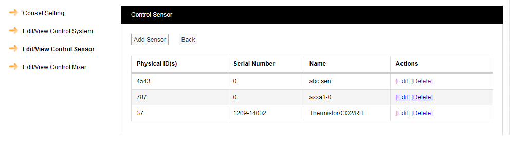
From this window you can:
•Edit a Control Sensor's Parameters
To Add a Control Sensor to the Control Group:
1.Click on the Add Sensor button.
•The Add Control Sensor window is displayed. See Figure 633 below:
Figure 633
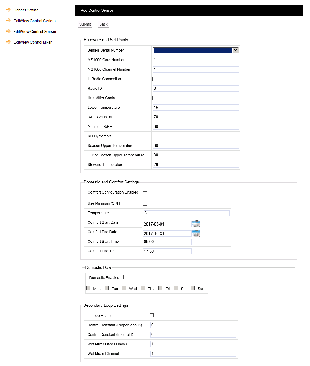
3.Enter the new Control Sensor's Serial Number into the Sensor Serial Number field or select an existing Sensor's Serial Number from the drop down list to use as a Control Sensor.
4.Add the required Control Sensor Parameter values for the new Control Sensor into the relevant fields.
5.Click on Submit.
•The Control Sensor window is displayed with a confirmation message. See Figure 634 below:
Figure 634
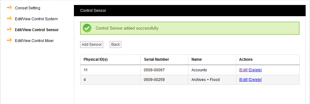
Click on [Delete] in the Actions column on the row containing the Control Sensor to be deleted.
To Edit a Control Sensor's Parameters:
1.Click on [Edit] in the Actions column on the row containing the Control Sensor to be edited.
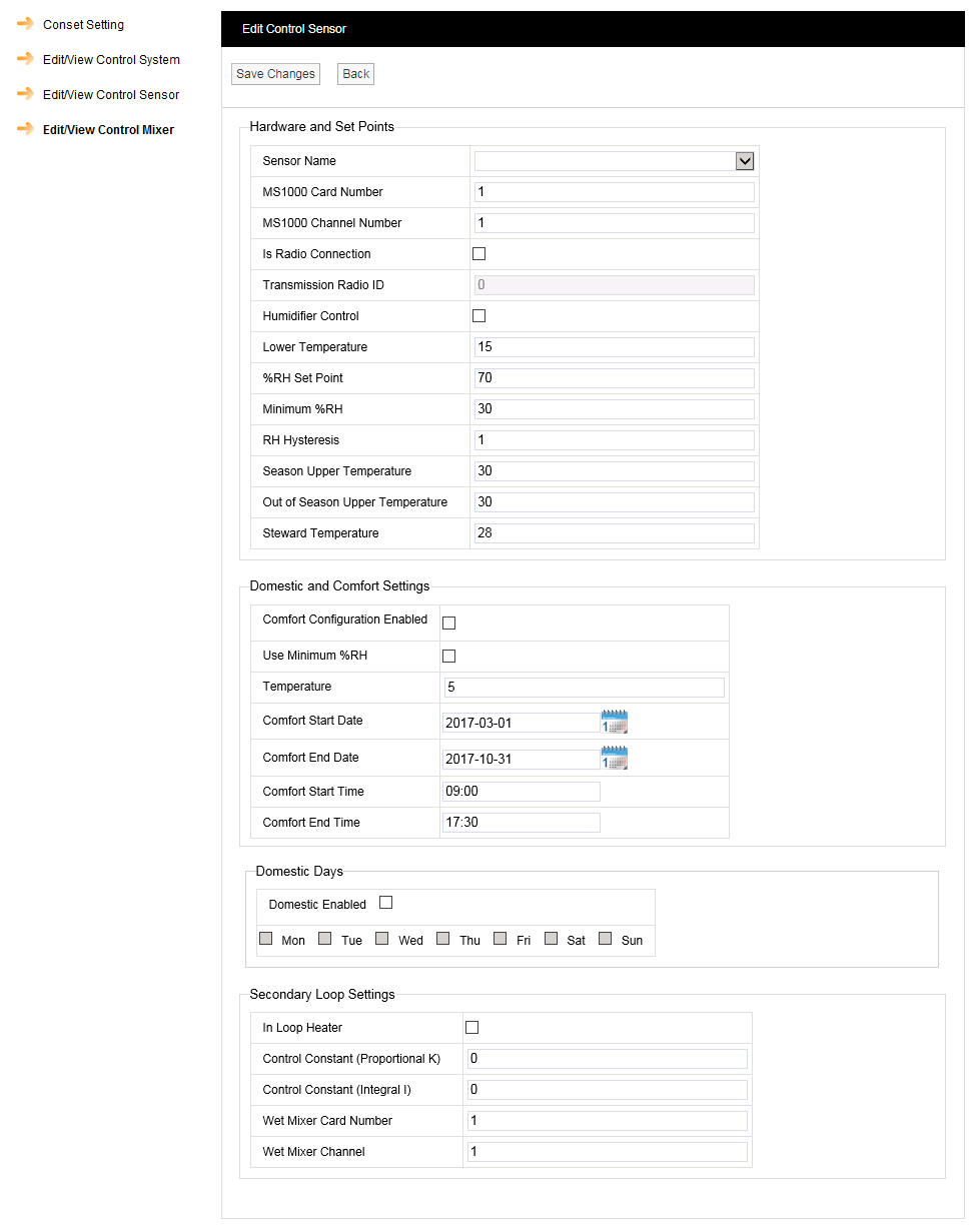
•The Edit Control Sensor window is displayed, showing the same Control Sensor parameters as displayed in the Add Control Sensor window above. See Figure 634 above and Figure 635:
Figure 635
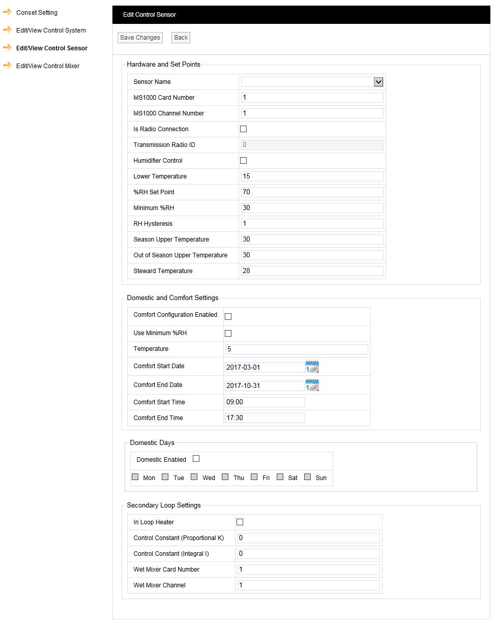
6.Enter an existing Control Sensor's Serial Number into the Sensor Serial Number field or select an existing Control Sensor's Serial Number from the drop down list.
•The Control Sensor parameter fields are populated with the selected Control Sensor's parameter values.
7.Edit the selected Control Sensor's values as required.
8.Click on Save Changes.
•The Control Sensor window is displayed with a confirmation message. See Figure 636 below:
Figure 636
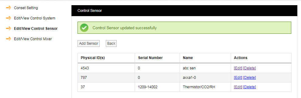
Figure 637
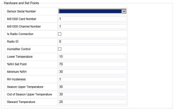
•Sensor Serial Number
The Serial Number of the new/edited Sensor.
•MS1000 Card Number
This is the card number of the MS1000 card controlled by the Sensor.
If the Sensor is not controlling any outputs, this value should be set to 0 (zero). When this value is set to 0, no settings will be displayed.
See Document Number: GD4619-1 MS1000 Control System Manual
•MS1000 Channel Number
Defines the MS1000 Output Channel that the selected Sensor is controlling.
If the Sensor is not controlling any outputs, this should be set to 0 (zero). When this value is set to 0, no settings will be displayed.
Note: If transferring from a RadioLog System, Channel allocations will no longer be defined solely by a Channel Number but will, instead, be defined by the MS1000 Card Number and that Card's MS1000 Channel Number. See Figure 637 above.
See the table below for Channel numbering definitions in RadioLog compared to Synergy:
RadioLog Channel Numbering |
Synergy Channel Numbering |
|
RadioLog Channel Number |
Synergy Card Number |
Synergy Card Channel Number |
1 |
Card 1 |
1 |
2 |
Card 1 |
2 |
3 |
Card 1 |
3 |
4 |
Card 1 |
4 |
5 |
Card 2 |
1 |
6 |
Card 2 |
2 |
7 |
Card 2 |
3 |
8 |
Card 2 |
4 |
9 |
Card 3 |
1 |
10 |
Card 3 |
2 |
11 |
Card 3 |
3 |
12 |
Card 3 |
4 |
13 |
Card 4 |
1 |
14 |
Card 4 |
2 |
15 |
Card 4 |
3 |
16 |
Card 4 |
4 |
•Is Radio
If the channel is controlled by radio transmissions from the CR3 (CR2 NW), the Is Radio box should be checked.
If the selected Sensor is hardwired to the Control Unit, rather than communicating wirelessly, the Is Radio box should be left unchecked.
•Radio ID
The ID of the selected wireless Sensor.
•Valid radio IDs are 1 to 254.
•0 is used to represent radio off (no wireless connection).
•Humidifier Control
Check the Humidifier Control box if the selected Sensor is controlling a Humidifier.
•Lower Temperature
If this temperature is reached, the heating will automatically switch ON, regardless of the RH control requirements. This prevents under-heating or frost-damage of an area.
•The default value is 15oC.
This is the %RH point at which the heating will be turned on to drive down humidity, irrespective of the Steward Temperature setting.
•Use Minimum %RH
The value overrides the Domestic and Comfort Settings.
If this Temperature value is reached during the season set in the Domestic and Comfort Settings box, the heating will automatically switch off, regardless of the RH control requirements. This prevents the overheating of an area.
•The default value is 22OC.
•Minimum %RH
This setting also has an optional Min RH value. This setting overrides the Steward Temperature so that the RH never drops below the Minimum % RH set here. This is to prevent over-drying of an area.
•The default value is 40%RH.
This value represents the 'width'/sensitivity of the RH switching band.
For Example: If a Hysteresis of 1 is set and the RH Setpoint is 55 (%) then the system will turn a heater on at 56%RH and off at 54%RH.
•Season Upper Temperature
If this Temperature value is reached during the Season dates/ times set in the Opening Hours Edit/View Control System window, the heating will automatically switch off, regardless of the RH control requirements. This prevents the overheating of an area.
•The default value is 22OC.
•Out of Season Upper Temperature
If this Temperature value is reached outside the Season dates/ times set in the Opening Hours Edit/View Control System window, the heating will automatically switch off, regardless of the RH control requirements. This prevents the overheating of an area.
•The default value is also 22OC.
This option allows a different Lower Temperature value to be set during opening hours, for human comfort, and can be specified as part of a Comfort Heating Scheme.
The software will use this setting during Opening Times/ Days (see the Site Details settings).
•This value should be higher than the Lower Temperature setting.
•The default value is 15OC.
| Note: | The, optional, Min % RH value overrides the Steward Temperature so that the Relative Humidity never drops below the Minimum % RH set here. This is to prevent over-drying of an area. The default value is 40% RH. |
It is possible to set temporary or permanent overrides of the optimum Conservation Heating settings - defined in the Hardware and Setpoints section to create an optimum conservation environment - to allow for events running outside standard opening hours or to accommodate offices or domestic areas.
If these parameters are set - Comfort Configuration Enabled box ticked - the selected sensors will then be activated for Comfort Heating within the set time span. See Figure 638 below:
Figure 638
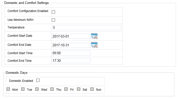
•Comfort Configuration Enabled
Ticking this box allows the setting of permanent or temporary overrides to conservation-optimum temperature settings.
•Use Minimum %RH
If this Minimum %RH value is reached during the Season dates/ times set in the Opening Hours Edit/View Control System window, the heating will automatically switch off, regardless of the RH control requirements. This prevents the overheating of an area.
•Temperature
Defines the Comfort/Steward Temperature.
•Comfort Start Date
Start date of the Comfort Temperature override of the settings.
•Comfort End Date
End date of the Comfort Temperature override of the Conservation Heating settings.
•Comfort Start Time
Start time of the Comfort Temperature override of the Conservation Heating settings.
•Comfort End Time
End time of the Comfort Temperature override of the Conservation Heating settings.
•Domestic Enabled
If the Comfort override is being used to control an office or domestic area, tick the Domestic Enabled box and then select the relevant Domestic Days by ticking the appropriate boxes. The Comfort override will then operate between the Comfort Start Date and Comfort End Date on these days of the week for all future weeks.
•No date settings are required in this case.
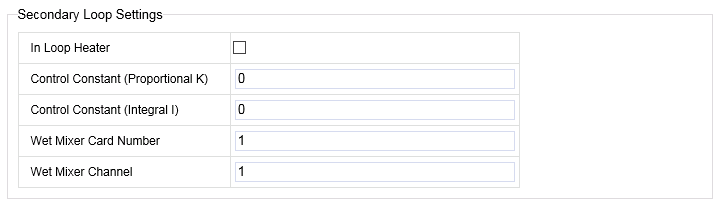
•In Loop Heater
If the target device is a wet radiator (rather than electric) then this box should be checked.
This is used to generate the Boiler demand signal.
•Control Constant (Proportional K)
This setting adjusts the proportional control's Controller Gain (Kc); a higher controller gain increasing the amount of proportional control action for a given error.
•If the controller gain is set too high the control loop will begin oscillating and become unstable.
•If the controller gain is set too low, it will not respond adequately to disturbances or Set Point changes.
The Proportional Control Constant is the main parameter determining ongoing humidity control.
•Control Constant (Integral I)
This setting (the integral term) increases action in relation not only to the error but also the time for which it has persisted. So, if the applied force is not enough to bring the error to zero, this force will be increased as time passes.
The Integral Control Constant refines ongoing humidity control towards zero static error.
| Note: | If the output channel is an analogue card controlling a mixer valve in a wet heating system then the K and I coefficients of the PI control algorithm are set here, otherwise they MUST be left at 0. |
•Wet Mixer Card Number
Defines the number of the MS1000 card controlling the channel which sends signals to a secondary heating circuit's motorised valve to allow temperature control by mixing water from the primary and secondary circuits.
•Wet Mixer Channel
Defines the MS1000 Output Channel that the selected Sensor is controlling/providing input to.
Accessing Mixer Settings for a Device/Control Group
1.Either:
Click on [Mixer Settings] adjacent to the required group's entry in the View Conset Groups window.
Or:
Select Edit/View Control Mixer from the left hand menu, visible if you have previously edited a Conset setting.
The Control Mixer window is displayed. See Figure 639 below:
Figure 639
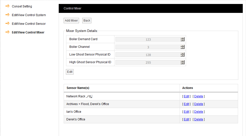
From this window you can:
•Return to the View Conset Groups Window
•Edit the Mixer System Details
•Edit/Delete a Control Mixer Sensor
1.Click on the Add Mixer button.
2.The Add Control Mixer window is displayed. See Figure 640 below:
Figure 640
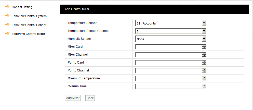
3.Select the Control Mixer parameters' values from the relevant drop down lists/up-down arrows:
•Temperature Sensor
The ID and name of the Sensor controlling the Secondary Loop.
•Temperature Sensor Channel
The channel of the Temperature Sensor on this loop.
•Humidity Sensor
The ID of the room sensor controlling this loop.
•Mixer Card
The ID of the MS1000 output card controlling this mixer (1 - 253).
•Mixer Channel
The channel of the MS1000 output card controlling this mixer (1 - 4).
•Pump Card
The ID of the MS1000 output card controlling the associated pump (1 - 253).
•Pump Channel
The channel of the MS1000 output card controlling the associated pump (1 - 4).
•Maximum Temperature
The maximum permitted secondary flow temperature (OC).
•Overrun Time
The time in minutes the pump should overrun after mixer valve closure.
4.Click on the Add Mixer button.
Return to the View Conset Groups Window
Click on the Back button.
1.Click on the Edit button.
2.The Edit Mixer System Settings window is displayed. See Figure 641 below:
Figure 641
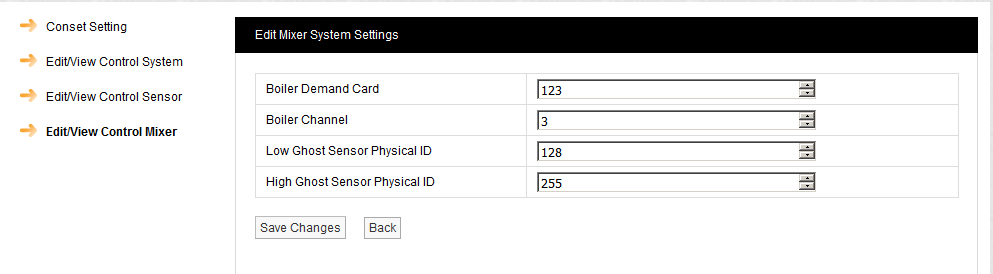
Boiler Demand Card
Defines the number of the MS1000 card controlling the channel which sends signals to the secondary heating circuit's boiler.
Boiler Channel
Defines the MS1000 Output Channel that controls the secondary heating circuit's boiler.
In Synergy, one sensor is associated with one channel only. However, there are circumstances where more than one control output is required per sensor. Examples are when a humidifier AND dehumidifier/heater are in the same room. Sensors can be ghosted to allow two channels to be controlled by one RH sensor, i.e. more than one control output per sensor. This can allow one sensor to control two pieces of equipment without installing a second physical sensor.
|
Defines the lower limit of the range of ghosted sensor IDs
In Synergy, one sensor is associated with one channel only. However there are circumstances where more than one control output is required per sensor. Examples are when a humidifier AND dehumidifier/heater are in the same room. Sensors can be ghosted to allow two channels to be controlled by one RH sensor, i.e. more than one control output per sensor. This can allow one sensor to control two pieces of equipment without installing a second physical sensor.
|
Defines the upper limit of the range of ghosted sensor IDs
Edit/Delete a Control Mixer Sensor
To Edit a Control Mixer Sensor
1.In the Actions column of the Sensor Name(s) list, click on [Edit] in the row containing the sensor to be edited.
2.The Edit Control Mixer window is displayed. See Figure 642 below:
Figure 642
3.Select the Control Mixer sensor's parameters from the relevant drop down lists/up-down arrows.
These are the same parameters
4.Click on the Update Mixer button.
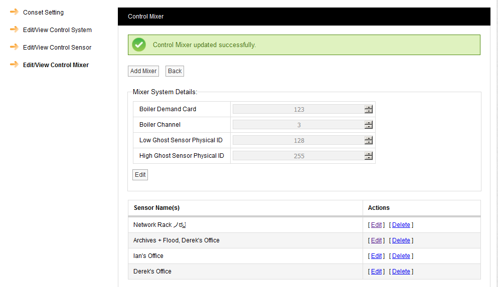
•The Control Mixer window is displayed with a message confirming the successful update. See Figure 643 below:
Figure 643
To Delete a Sensor
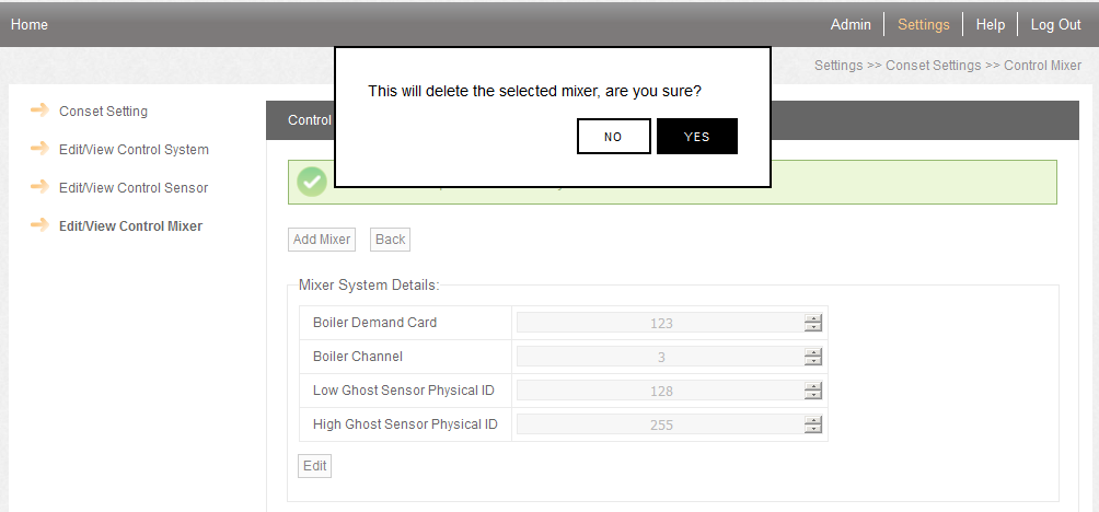
1.In the Actions column of the Sensor Name(s) list, click on [Delete] in the row containing the sensor to be deleted.
2.Click on Yes in the displayed warning window. See Figure 644 below:
Figure 644