Navigation:
»No topics above this level«Introduction to Synergy

Contents
Synergy provides a browser based User Interface for Hanwell wireless monitoring installations.
Synergy offers a wide range of User options and configurations, ensuring future proofing and ready customisation to the User's particular circumstances.
Given the necessary permissions, Synergy allows the User to rapidly change options and configuration details.
Synergy has two key functionality strands:
•Extensive Reporting and Logging capabilities with custom reports available as easily accessible plug-ins to the main system and the capability to transmit Alerts.
•The ability to act as an interface between Hanwell wireless monitoring equipment and 3rd party control equipment such as motorised valves and alarm sounders.
•Browser Based Graphical User Interface (GUI) •Scaleable Application |
•Main Concepts and Architecture
•Data |
•Synergy Management Tools and Remote Management Tools
Browser Based Graphical User Interface (GUI)
Synergy employs a browser based GUI (Graphical User Interface) which is totally separate from the underlying hardware and allows Users to connect from any commercially available browser, such as Explorer or Firefox, and access data via an Intranet or, optionally, over the Internet.
| Note: | The Host machine and Client machines MUST have one of the following browsers installed: |
•Internet Explorer 8, 9, 10 or 11.
•Microsoft Edge (Windows 10).
•Google Chrome Version 29 or later.
•Mozilla Firefox Version 23, 24, 25, 26 or later.
Support for Browsers is unlikely to end, especially given the numerous companies involved in their creation, maintenance and development. Therefore the risk of problems caused by Operating System Providers ceasing product support or even going out of business is minimised.
Synergy uses an SQL database making it easy to quickly and efficiently manage and access large amounts of data.
•SQL databases use well defined standards, which are being adopted by ANSI & ISO, enabling an SQL database to be used by 3rd-party tools if required/commercially desirable.
•Synergy is shipped in two variants to allow for differing locations and installations of the SQL database: W700A and W700B.
Synergy can be provided as an A or a B install. Which one is appropriate needs to be decided before installing Synergy as each requires different pre-requisites to be in place. •An A install puts the SQL database on the same Target Server (i.e. where data is sent to from the Control Devices) as the Synergy software. If the Target Server does NOT have an existing Microsoft SQL Server instance and you do not wish to use and/or have an appropriate Microsoft SQL Server available on the LAN, then Synergy W700A / W706A is required. •A B install puts the SQL database on another machine/server from the Target Server (i.e. where data is sent to from the Control Devices). If there is an existing Microsoft SQL Server on the Target Server or LAN that you wish to use for Synergy, then Synergy W700B / W706B is required. |
Synergy is a Scalable Application and can be installed on a single site with 1 User up to 100s or sites with 1000s of users, allowing seamless support for both large numbers of sensor communication protocols and very large numbers of sensors over multiple sites.
•Synergy allows you to select any combination(s) of sensors to form Groups, i.e. sub-sets of the group of all sensors in a Synergy system, with all subsequent operations (alarms, reporting etc) only operating on that subset.
•Synergy gives you control of exception handling protocols; the various options do not have to be generically configured by the Administrator.
•Synergy is a services-based system.
•Synergy's architecture ensures that support for as yet unknown hardware can be readily integrated (future proofing) by modularising the hardware services and accessing the database via a universal interface module.
Main Concepts and Architecture
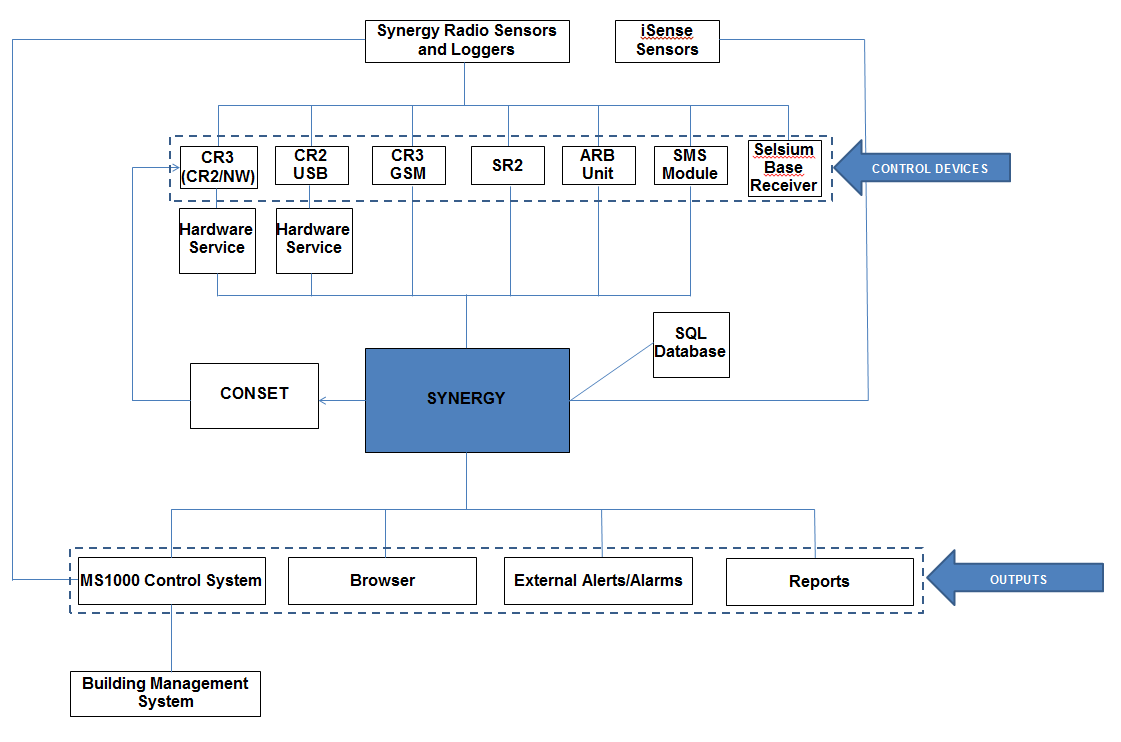
Data input to Synergy is mainly generated by wireless Hanwell Sensors and Loggers which collect data/readings at the Site Synergy works with the Hanwell 12bit RL, ML and HL ranges of Radio Sensor Transmitters and Loggers. Note: Synergy is not compatible with legacy 8 and 10 bit devices. iSense sensors can be used to remotely collect and transfer sensor readings to the Synergy system via the cellular telephone network. iSense sensors are handled as a special sensor in Synergy; they are not part of a Control Device Group and have a special PID value of zero. Synergy collects iSense data by making an outgoing TCP/IP connection to the IMC Remote Data Service. As this connection is made to the standard HTTP Port – 8081 - on the IMC Remote Data Service, the System operates in the vast majority of cases with no need to make network or Firewall configuration changes. |
Control Devices relay data acquired by the Sensors and Loggers to the Synergy Server by TCP/IP (Internet or Intranet), USB connector and cable or GPRS (mobile/cellular phone network). The collected data is then stored in Synergy's associated SQL Database and made available for viewing via a Local Management Application or a standard Web Browser. There are several types of Control Device (more maybe added in the future): •SR2
•CR2
•A Control Device Group is a named collection of one or more Control Devices and associated sensors. •A Control Device Group defines the polling interval for Control Devices in the Group. •CR2 and CR3 devices each have their own Control Device Group; whereas multiple SR2s can be used in a single group. •Within a Control Device Group, all sensors and Control Devices must operate on the same frequency. •This will only apply to multiple SR2s as single CR2 and CR3 Control Devices, and their associated sensors, in their own Control Device Group (see above) will only operate on a single frequency. i.e: Groups of sensors and SR2s on the same frequency can be in one or more Control Device Groups; but a single Control Device Group must not contain SR2s and sensors on more than one frequency. All sensors associated with a Control Device Group must have a unique PID in the range 1 to 254; e.g. there can only be 254 sensors in a Control Device Group (see iSense Sensors however). Where a system uses multiple sensor frequencies, sensor PIDs can be duplicated/shared between different frequencies but the sensors on each frequency will need to be allocated to separate Control Device Groups. |
Synergy introduces the concepts of Sites and Zones.
•The allocation of Sites enables the collection of data from distributed systems and locations and allows the connection of multiple distributed data collection devices to a Synergy installation.
•Sites are the main access points to the System Data.
•Each Site represents a single physical location where receiving Control Devices such as SR2 Smart Receivers, CR2 or CR3 Controllers are sited, along with measuring Sensors and their associated Transmitters.
•A Synergy System can encompass numerous distributed Sites.
| Note: | More than two Sites will require additional licencing. |
•Sites can have Sub-Sites; there is no functional difference between a Site and a Sub-Site.
•Different Sites can be on different time zones; where this is the case, displayed sensor data will reflect the local time for the site.
•Zones are used to logically group sensors.
•Sites can have Sensors grouped together into Zones. Zones replace the grid system previously used in RadioLog.
Synergy Outputs
Sensor Data Viewing and Reporting
Synergy has been designed to be able to accommodate Custom Plug-in Reports of information generated from, and related to, the System's Sensor/Transmitters. •The reports can be tailored to the Customer’s individual specifications and generated at the click of an on-screen button in PDF format, with the option to have a .CSV data file attached. Additionally, User Configurable Scheduled Reports can be generated and, once configured, be auto-generated on a daily, weekly or monthly basis and sent to the User by email. •Scheduled Reports can be downloaded and saved in PDF format. Your Company Logo can be automatically added to any standard (PDF or RTF) report. Four types of Report are available: |
User Alerts provide automated Alert notifications; delivered via Email, SMS or both.
The Synergy system enables the use of password authenticated accounts to login to SMTP & POP3 / IMAP servers. Synergy can also be set to use SSL / TLS to secure email server connections. The email account password is stored as encrypted data, using a machine specific key; as such, moving Synergy data from one machine to another will break the key and the password will need to be reset using the Email Alert Global Settings screen in a browser. If required, assuming a suitable POP3 or IMAP email server is available, the Synergy system can be configured to enable the use of email replies to acknowledge Alarm alerts. Synergy’s Email Alert Groups system is very flexible, allowing multiple groups to be set up with different sensors, alarm types and active days or times for sending SMS alerts to various recipients. Different recipients can be set to receive SMS for different alarm types on the same sensor and / or for alarms occurring at different times of the day. Alerts can also be emailed for various system events (see below). When used with an SMS Module, Synergy can send SMS alerts in response to sensor alarms, various system events (see below) and power or network communications failure. Synergy’s SMS Alert Groups feature is very flexible, allowing multiple groups to have different sensors, alarm types and active days or times, for sending SMS alerts to various recipients, to be defined. •Different recipients can be set to receive SMS for different alarm types on the same sensor and/or for alarms occurring at different times of the day.
System Alerts can be sent (via Email or SMS) in response to: •System Start up (includes previous System Shutdown information); •Login Fail; •System Edit; •Hardware Events (e.g. an SR2 going offline). •System Stop Alert Synergy is a web-based product, with a number of backend services, running on a server; a User closing the programme cannot shut it down. However, there are three possible shutdown scenarios: •Software failure; •Administrator action; •Power failure. In order to facilitate fast shutdown, reducing the risk of consequential data loss, following one of the above three scenarios, the Data Service detects and writes details of a shutdown to an XML file. This file is then used to generate an Activity Log entry, which the Data Service will then send as part of a System Start Up SMS / Email Alert when the System is next started. |
Management and Monitoring of 3rd Party Control Equipment
The Hanwell MS1000 Control System provides an interface between Synergy and 3rd party control equipment and alarm sounders.
Synergy Management Tools and Remote Management Tools
The Synergy Management Tools and Synergy Remote Management Tools are a collection of applications that enable direct Communication Setup and Configuration tasks that cannot be performed from a browser.
The Synergy Management Tools are a collection of applications that enable Synergy Administrators direct access to the Synergy Server to perform Communication setup and Configuration tasks, that cannot be performed from a browser, on the Synergy Server or computers on the LAN local to the Synergy Server. |
Synergy Remote Management Tools enable Synergy Administrators to communicate with and perform Communication setup and Configuration tasks on computers that are remote from the Synergy Server. For example, Synergy Remote Management Tools would enable Synergy Administrators to synchronise sensors and setup SR2s on computers that are remote to the Synergy server.
|
Because Synergy’s Primary User Interface is browser based, allowing Users to connect from any browser on the local network and, potentially, from remote locations as well, all Users must login with a User Name and Password.
Synergy Passwords are case sensitive, Synergy User Names are not.